Group 05
Week One
April 2,2014
1. Form groups
- The group consists of: Kimberly Carden, Mary Hayles, Kelly McGuigan, Jaclyn Schachtner, and Andrew Wilson, all of whom are Biomedical Engineering students at Drexel University.
2. Discuss possible topics
- There were several topics which could be pursued during the duration of the ENGR 103 course. The options included: an artificial heart valve, app design in the areas of: a Electrocardiography Monitor, Sleep Apnea, Plethysmography, and an oxygen pulse oximeter, a robot to aid those with disabilities, and creating an artificial ear or nose.
3. Decide on project topic.
- Our group decided to design an artificial pulmonary valve for the human heart. Our design prototype will be developed using 3D plastic printing.
4. Research the functioning of the pulmonary valve, disorders of the pulmonary valve, and replacement of the pulmonary valve.
- The pulmonary valve is the valve responsible for allowing the flow of deoxygenated blood from the right ventricle to become oxygenated in the lungs. There are several issues pertaining to the pulmonary valve such as pulmonary valve stenosis and regurgitation. Current technology for replacing faulty pulmonary valves are: transplanting a valve from a cadaver, transplanting a valve from a pig, or using a mechanical valve. This project will explore different designs for mechanical valves. In a surgery called the Ross Procedure, the pulmonary valve is also commonly used to replace the aortic valve, because of this, the need for a suitable, well-functioning pulmonary valve is essential.
5a. Create group Google account. Create Blogger Account, and begin blog template for design project.
5b. Format and edit blog
- Not one of the group members was familiar with the Blogger interface or functioning, so a good deal of time this week was spent on bringing the group member's up to pace with how to edit the blog and all of the uses for the blog. Once a general understanding was found, several key pages were created as the framework for the blog, these pages included: Project Overview, Weekly Progress, Background, Tutorials, and FAQ's.
7. Create biographies on blog for each group member
8. Design Proposal Written Report
- While in lab, the group assigned portions of the written report to each member which would complete before meeting. Each member was assigned approximately two sections to complete; this was done to ensure that equal contribution would be seen in the report. The group met twice before meeting again in lab the following week to construct the final report.
Week Two
1. Research specific area for artificial valve
2. Calculate dimensions using continuity equation and researched values for valvular flow

- The continuity equation is used to approximate the surface area of a valve. This mathematical model is an underestimate; however, the information that can be used provide the closest approximation for the size of a valve. Several factors influence a heart valves size, such as the size, age, and athletic aptness of an individual; therefore the continuity equation was used to generalize the size of the pulmonary valve. For our purpose, this estimate would be sufficient enough for the prototype which will be produced.
 |
| Figure 1: Top View |
 |
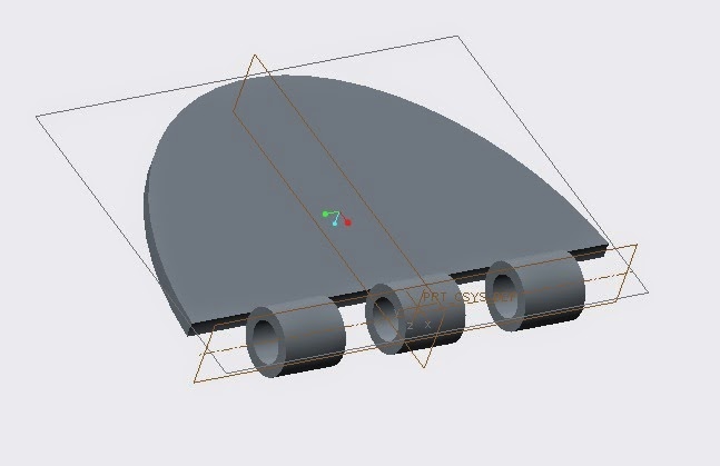
| Figure 2: Rotated View, showing the inner ledge and the rings that will mount the hinge for the inner mechanism |
The inner mechanism that will control blood flow still needs to be modeled. Then the separate parts will be assembled together. The design may also need to be modified as calculations are made regarding the flow of blood, the size of the valve, and the simulations that will be used to test the design's functionality.
Week 3
April 16, 2014
1. Update blog's tutorial, background, and FAQ sections
- New literature was acquired this week, so for the general maintenance of the site we updated some of the out of date information. Also, we decided that it was pertinent to the success of the project to make the blog as readable as possible; this was done to insure that any person would be able to read the blog and understand the goal, design, and necessary information behind our artificial pulmonary heart valve.
2. Finalize Creo design for outer ring of valve as shown in figure 3.
- It was concluded that a thinner outer ring would be more comfortable to the patient and less obstructive to the lining and functioning of the heart. A smaller height, of 4 mm, is more align with current valves that are being implanted; for obvious reasons, it appears as though designs with a smaller height allow for maximum blood flow and minimal discomfort or chance of a clot forming. With the previous design, which consisted of an artificial ring with a height of 8 mm, there was a greater chance that the body would reject the foreign material because the valve has a larger surface area which would come in contact with the lining of the heart; should the body identify the valve as an invasive material the result would be very detrimental to the human.
- Previously, our design was calculated off of the size of the mitral valve, partially because there is more literature on it and because our understanding was that the pulmonary valve and the mitral valve were of similar size; however, this week it was uncovered that, in lamens terms, the size of the mitral valve is approximately the size of a penny, while the pulmonary valve is more similar to the dimensions of a dime.
 |
| Figure 3: Modified Creo model of the outer ring from week 3 |
Week 4
April 23, 2014
1. Design the bi-fold leaflets (figures 4 and 5) and center rod (figure 6) of the valve in Creo
These leaflets will rest on the inner ledge of the outer ring part. The two leaflets will have corresponding hinge mechanisms. Therefore, the leaflets may fit together tightly to prevent any leakage. These parts will be mounted onto the outer ring by mounting a rod through the center of the two sides of the hinge mechanisms and through the mounts on the outer ring part. The center rod will be mounted in place by having one end have a cap on it so it will fit tightly into the mount of the outer ring. This design allows the two leaflets to be opened and closed depending on blood flow.
 |
| Figure 4: 3 hinge leaflet |
 |
| Figure 5: 4 hinge leaflet |
 |
| Figure 6: Center rod with cap highlighted in blue |
2. Look into Add-Ons provided by MathWorks and see which toolboxes would best meet the needs of the project.
- It was decided that SimHydraulics would best suit the project because it allows for different liquids to be tested through a system, allowing the team to select a fluid which is most similar to blood in density, and also provides a flowchart of how the system will function. SimHydraulics will be used to model the blood flow from the right ventricle through the pulmonary valve into the pulmonary artery and then finally to the lungs where the blood will become oxygenated. Once the flow model has been constructed, the system can be tested.
This video depicts a more mechanical system rather than biological system; however, the principles used in this video will be used in modelling blood flow for this project.
The team contacted MathWorks about a free trial use of this software; however, Mathworks does not supply this program to students.
Week 5
April 30, 2013
1. Finalize the first prototype of the artificial pulmonary valve (figures 7 and 8)
- All of the parts have been finished; this week is predominantly being used the assemble the pieces and ensure that they fit snugly inside one another. The intended goal is to have the first mock-up of the valve done and submitted to the 3-D printing lab by Thursday, May 1, 2014.
 |
| Figure 7: Assembled valve with all components closed |
 |
| Figure 8: Assembled valve with bi-fold leaflets opened |
2. Contact MathWorks regarding SimHydraulics.
- It was confirmed that Drexel University's site license does not cover the download and use of SimHydraulics, so this week the team contacted a Sales Representative from MathWorks about the use of this program. We are hoping for a quick reply, because the modelling aspect of this project needs to be underway to ensure that the design will be completed in five weeks.
3. Update the FAQ section of the blog
Week 6
May 7, 2014
1. Received 3-D print outs of artificial pulmonary valve
- Our original submission's dimensions were much too small to accurately have the 3-D printer print out the correct features. The model which printed out lacked the connecting rod which assembled the leaflets. Also, the hinges for the leaflets were not correctly printed; this was due to the inner dimension of the rings being infinitesimally small for the printer.
 |
| Figure 9. First submission of heart valve design |
2. Resize the Creo Part Files and Assembly
- Due to the misprinted valve, the group decided to enlarge the prototype by 10x. This was done to allow for a more functional model to be presented during the group's final presentation. The original prototype, which is slightly smaller than to scale, will still be used during the presentation to show the approximate size of an artificial valve, but also to show some design flaws.
3. Assign Duties for the Rough Draft of the Final Report Due Next Week
Week 7
May 14, 2014
1. Received 3-D print outs of the enlarged artificial pulmonary valve
- Our secondary submission's dimensions were increased by a scale of ten times the original submission's dimensions. This increase in size allowed the 3-D printer to print the model more accurately. All parts of the assembly were able to fit together with the exception of the hinges of the two leaflets. The hinge mechanism did not fit together because the 3-D printer left rough edges on the hinges. Therefore, the rough edges were sanded to make smooth edges. The hinges then fit together properly and were able to rotate around the center rod as expected.
 |
| Figure 10. Ring 3-D print of enlarged submission |
 |
| Figure 11. Rod 3-D print of enlarged submission |
 |
| Figure 12. Leaflet 3-D print of enlarged submission |
 |
| Figure 13. All parts of enlarged 3-D print submission |
2. Creo Parametric Simulate
- In order to test if our valve design is successful the group decided to test it using the Creo Parametric Simulate application. This application will test the durability of the mechanical valve by applying force to mimic blood flow out of the heart in addition to preventing back flow of blood. The simulation will mimic the conditions the valve would be under as if it were actually in the heart and determine if the valve will function appropriately. Due to the fact that the group is unfamiliar with this application of Creo Parametric, research had to be done on the operation of the application. Due to this unfamiliarity with the application, no conclusive data has yet to be collected.
3. MATLAB
-The first set of coding performed dealt with the relationship between the velocity of blood flow and the force which this blood flow would apply on the heart valve. The Figure below is a graph of this relationship.
 |
| Two different models were under speculation for the artificial pulmonary valve; both of which had the same design, but differed in the orientation of the leaflets. The upper, magenta, line represents the results of the design which was chosen for the project. The lower, black, line represents the reverse design; this design featured a radius of 0.17 inches and a length of 0.44 inches, the opposite of the design which was chosen. It was decided that a greater force exerted on the valve would be beneficial because the valve would be sure to react to the pressing of the blood against the valve.
Week 8
May 21, 2014
1. Refine second 3-D print submission.
-Our second 3-D print submission was much larger and more functional than our first submission. Although the second submission was more successful, when we attempted to assemble it did not rotate as smoothly as wished. In order to take care of this problem we utilized sandpaper. We smoothed and refined the hinges of the leaflets. This eased the rotation of the leaflets. In addition to this we used sandpaper on the rod to remove the rough bumps on it. The 3-D printer did print our submission accurately but not perfectly. This resulted in excess bumps on the rod, inhibiting a completely smooth rotation of the leaflets. This was easily fixed with the use of sandpaper.
2. Final Presentation
- This project is coming close to completion. In order to display our progress, results and design we are compiling a final presentation.
- Each member was given a few tasks to complete in regards to the presentation. These tasks will be reviewed by the other teammates in the future.
- The final presentation will continued to be worked with during the next two week.
Week 9 May 28, 2014 1. Final Presentation and Report - The group is finishing the final presentation by reviewing the power point and making any necessary revisions. The group has also compiled a final report that follows the content of the power point presentation, but goes more in depth with technical details and explanations of the ten week process. The final report will be an expanded explanation of the technical aspects of the project. -The group is also putting together a demonstration which will be recorded and included in the presentation. Week 10 June 4, 2014 1. Presentation - The final presentation will take place in a conference room, which will be open to any Drexel students, faculty, and staff. - The group plans to bring the enlarged model to the presentation to use as a visual aid. |
No comments:
Post a Comment